
Wednesday, August 29, 2012
Single Channel PCIe Board
Here is the full layout of the Single Channel PCIe board. A PLX PEX8311 is sitting on top of the PCIe Bus, and there is a Xilinx XCS20 as the Local Bus Master. The PCIe interface is LVDS at high clock rates, so the board needed to be controlled impedance. The stackup is really important in this matter. Keeping your signals out of the wind makes a happy circuit board...

Tuesday, August 28, 2012
Dogboned BGA
This is the PCIe board that I have been working on for a while. Its the one with the Xilinx FPGA, and then the chip in question is a PEX8311 from PLX. Its a 377 pin, 1mm pitch, micro BGA. Its also the first BGA package I've put on a design. This is the first fanout of the BGA. I used Via in Pad techniques that ultimately led to a lot of manufacturing trouble.
 This is what I am calling a Pinned BGA. I figured that a direct connect approach was best so I designed a through hole padstack to mount a BGA. The idea was to fill the holes and finish plate the top of the padstack where the BGAs solder ball are attached. This worked good the first couple of times we manufactured these boards, at a shop that had the filled and plated via capability. The third time we fabricated these boards, at a shop that did not have filled and plated via capability, there was big trouble. The boards got to the people that do the BGA assembly, and got rejected. We spent a lot of time trying to rectify this problem. So, now I am reworking this board to use regular vias, and loosing my fancy padstack.
 This is the revision layout. We did a typical BGA fanout on a 1mm grid. The BGA pads are only on the top of the board, and we get all the signals down to the layer with a via. The outer two layers of the BGA can fanout on the surface, and they don't necessarily need vias. This technique frees up space under the BGA for routing control and power traces. This design is also matched impedance with all signal layers only about 5 mils from a plane. Oh yeah, this fanout technique is called dogboning a BGA...


Monday, August 13, 2012
Trimmer Fuel Lines
During the process of replacing the Starter string on the String Trimmer I had some tuning issues with the Fuel System. In the process of trying to tune the carburetor I managed to crack one of the fuel lines.
 The last time I replaced the fuel lines was a couple years ago when I had taken the String Trimmer to Mower Medic for a tune up. Before pulling the old lines off I wanted to take note of where they are attached to the carburetor, and differentiate the lines in the tank.
 The first line I am going to work on is the primer return line. The primer circuit pulls fresh gasoline into the carburetor before starting. This fuel line send the extra gasoline back to the tank. This is the line that is cracked also. I'll pull the old line out of the tank and off the carburetor, and then cut a couple pieces of new lines to replace them. There is a fitting there to connect the two lines together.
 The second fuel line is the source line for the carburetor, which has a filter on its input which lives in the tank. When replacing this line you need to start with a piece that is about six inches longer than it needs to be. This is because we need to install the filter on the end of the line, in the tank.
 I removed the fitting and the filter from the old fuel line, then measured and cut new pieces of fuel line.
 I push the in tank fuel line almost all the way through the tank, so that I can grasp the in tank end of the fuel line to install the fuel filter. Then we'll install the fuel filter, and pull the fuel line back out of the tank, over by the carburetor, until the filter is in the middle of the tank.
 Next we'll trim this line about the same height as the other in tank line, and add the carburetor end of the fuel line. This is a dual tube fuel line setup because the grey tubing has a better outside diameter for sealing in the tank, and the green (Tygon) tubing has a slightly tighter inside diameter for fitting on the nipples on the carburetor.
 Now that the new fuel lines are installed I would normally test the String Trimmer right away, but there is another problem that is directly associated with the fuel lines, and primer system. The primer bulb is cracked.
 This bulb is the pump which primes the carburetor for starting. Obviously chen its cracked its not going to do its job, because its not sealed, and leak gasoline all over the place.
 There are two screws that secure the primer bulb with the clamp plate. These two screws also hold the body of the carburetor together, so you don't want to move the trimmer around when the carburetor is open. When putting the carburetor back together, make sure that the carburetor pieces, and gaskets are aligned before torquing down the bulb clamp plate screws.
 Now, with the fuel primer bulb repaired we can finally test our new fuel system components. This is not a full fuel system rebuild, just patching a few things here, which is the norm on this decade old String Trimmer. A full rebuild would include a carburetor kit, which includes gaskets and small parts to rebuild the carburetor, and we would replace the fuel filter as well. While we're in here, don't forget to clean and oil the air filter.


Compressor Emergency
The Air Conditioner quit working again, this time its 105 F outside, and we're it the panic state of mind. Total Crisis. After all the bias that I have been fed about my old Carrier Condenser unit, we were expecting it to fail any minute. Large electromechanical companies that have worked on this unit have been telling me the same thing for years. That old unit is shot, you better buy a new one. I had become leery of their advise, after a decade of the unit not dying. every time it failed it was a capacitor. Then we had an independent guy take a look at it, and he said the condenser is in really good shape for its age.
 This time it was the compressor capacitor, and it wasn't just weak, it failed. The compressor stopped working, and it sent us into panic mode thinking that the compressor failed, and that is a very expensive part. I had a thought before I started calling electromechanical people to replace that cap, which would have been relatively inexpensive, maybe $25 at Turner Hardware. But because I allowed myself to panic, I called several place for a quote on a new system, which turned into a traumatic day. In the end it was Bill McKenna from Cooling Texas that identified the faulty capacitor, and replaced it without all the guff about the system being old, and you have to replace the whole thing. What a relief, honesty, and refrigerated air...
You can contact Bill McKenna at 972-805-7770, and the website is Cooling Texas

You can contact Bill McKenna at 972-805-7770, and the website is Cooling Texas
Sunday, August 12, 2012
Trimmer Starter
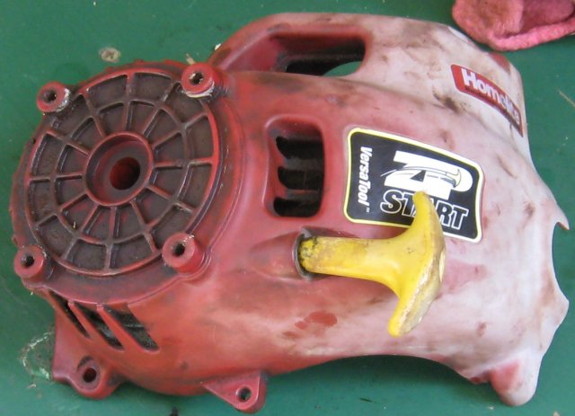
I'm out there in the yard on Saturday afternoon, getting ready to trim the edges. I pull on the String Trimmers cord, and pull it right out of the Trimmer. Fork! We'll its not the first time I have done this. Actually its getting kinda routine. My Homelite Versa Tool was manufactured in 2001, so its got a few miles...
 The starter assembly is right next to the motor, under the shaft boom, so we'll have to take the Trimmer nearly all the way apart to get to the starter assembly. The first thing to come off is the tool assembly, or the trimmer head. It has a quick connector which is a clamp and a button.
 There are other tool assemblies available for this this power module such as an edger and a blower. Next we'll take the primary boom off the power module. Here we'll need to disconnect the throttle cable and the electric shut off switch. Then there are four screws the hold the boom onto the power module.
 All of the screws on this Trimmer are T-25 Torx Screws. I had to buy a set at the Cheap Tool Store, but in one instance the shaft of the driver was loo large, and I had to modify it. To remove the throttle cable I needed to remove on of the cowling screws that has a bracket that holds the throttle cable. Then the electric shutoff switch has a couple of quick disconnects.
 Now we're down to the clutch. This is where I had to modify the T-25 Torx driver shaft. It was too large to go down into the clutch bellhousing. To extract the clutch bellhousing you need to unscrew the screw inside of the bellhousing. Also you need to secure the crankshaft so that you can unlock the bellhousing screw. I take a screwdriver, ad insert it between the vanes on the flywheel, and wedge it in the cowling. This allows you to torque the screw, without rotating the crankshaft.
 Now we're down to the Centrifugal Clutch. I had a little trouble here this time. When I first reassembled the Trimmer the clutch wouldn't engage, and after a little troubleshooting I found the clutch plates we're rusty, and sticking to each other.
 I rectified this by sanding down with the clutch plates with course grit garnet paper. I had tried to add some Lithium Grease to make sure they wouldn't stick, but that ultimately caused clutch slippage, so after I cleaned off the grease the clutch is working good again. Now we can remove the cowling to get to the starter.
 There are two pieces to the cowling, and the back comes off first with two screws. Then the front has another three screws, and that is where the starter assembly is located.
 The starter is a spring loaded return spool which actuates a pawl drive system. This means that when you pull the string the pawls engage, and turn the shaft, but if the shaft is turning, then the pawls are disengaged by centrifugal force. There is a plate which holds the sing loaded starter in place.
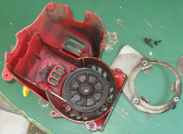 The starter pulley has a sprocket on it that catches the pawls on the flywheel, and spins the shaft when you pull the cord. This pulley is now loose, and can unwind if you let it. Also there is a coiled return spring under the starter pulley. Be careful not to disturb the return spring.it will sproing all over the place.
 Once the Starter Pulley is free we can remove the old cord and replace it with a new one. Take note of the direction the cord is wound on the pulley and wind it back in the same direction. The cord is held in place with a half hitch knot. The cut end of the Nylon rope can be sealed, or terminated with a flame. I usually take a lighter and melt the cut end of the Nylon rope.
 After the Starter String is replaced then we'll reassemble in reverse order. Once the Stater spring, pulley, and support plate are reinstalled, then we need to pretension the string, and install the pull handle. When I rewound the Stater Pulley I used extra cord for this purpose. Pull the cord out of the starter until there is a slight tension on the cord, then clamp the cord to prevent it from returning into the starter.
 The we'll push the starter handle up to were the clamp is. Make a half hitch knot to secure the starter handle.

 Now the actual repair is completed, so now we can reassemble the string trimmer. Here I am going to spend a little time cleaning the unit up before reassembly. There is at least a couple years of krud built up on it since the last time I changed the starter cord.
 The first thing to go back together is the cowling. Three screws for the front, and another two in back.
 Next the clutch plates go back on, no grease this time. You don't have to torque these down. The shaft spins counter-clockwise from this perspective. The power of the motor will torque the clutch plates into place because the screw in right handed, screws down clockwise.
 The clutch bellhousing is next, remember we need to lock the crankshaft when torquing the bellhousing screw.
 Then we'll replace the transmission boom, which transmist the power from the motor to the tool assembly.
 Reconnect the throttle cable, electric shutoff switch, and the tool assembly and I think we're good to go.
 It ran the first time I pulled the cord. This time without the clutch slippage problem. I think we're back to String Trimmer homeostasis...


Then we'll trim the Nylon cord, and terminate the cut end with a flame, like a pocket lighter.


Condenser Fan
Its Memorial day, 95 degrees Fahrenheit outside, and the Air Conditioner
quit working. We knew that the Compressor Fan motor bearings were
dying, making squealing and grinding noises. Well last night (Sunday)
it quit running. No way to get parts on Sunday night, and today is
Memorial Day so none of the Industrial Supply places are open. Last
week we had the air Conditioner company give us a quote to replace the
Compressor Fan motor, and it was $670! We decided to wait until the
motor failed.
 No Air Conditioning makes some people in my house very cranky. So I
really needed to get this fixed pronto today, and had to find someplace
that was open who would have a quarter horsepower, single phase, AC
motor. Turner Hardware in Farmers Branch came to the rescue, again.
They had the right motor, and the matching capacitor it needed. This is
a universal motor, so it required that I modify it a little for this
application.
No Air Conditioning makes some people in my house very cranky. So I
really needed to get this fixed pronto today, and had to find someplace
that was open who would have a quarter horsepower, single phase, AC
motor. Turner Hardware in Farmers Branch came to the rescue, again.
They had the right motor, and the matching capacitor it needed. This is
a universal motor, so it required that I modify it a little for this
application.
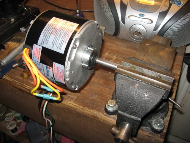 I needed to trim the case bolts, and also cut the shaft to the length on
the original motor. It was fairly easy to trim the case bolts and the
shaft with a hacksaw. The motor is mounted from the backside, and the
shaft points down when its mounted in the Air Conditioner chassis.
I needed to trim the case bolts, and also cut the shaft to the length on
the original motor. It was fairly easy to trim the case bolts and the
shaft with a hacksaw. The motor is mounted from the backside, and the
shaft points down when its mounted in the Air Conditioner chassis.
 There are four wires that go to the electrical control box, a ground
wire, and a couple of wire to control the direction of rotation. It is a
proper replacement, so I didn't need to alter the mounting, and it fit
the same holes. There is a conduit which routes the AC wires away from
the fan. The ground wire needed to be attached to the chassis in close
proximity to the motor. I used a sheet metal screw to secure the ground
wire to the sheet metal frame. I used a couple tie wraps to secure the
direction control wires to the louvers on the top of the assembly,
keeping them away from the fan.
There are four wires that go to the electrical control box, a ground
wire, and a couple of wire to control the direction of rotation. It is a
proper replacement, so I didn't need to alter the mounting, and it fit
the same holes. There is a conduit which routes the AC wires away from
the fan. The ground wire needed to be attached to the chassis in close
proximity to the motor. I used a sheet metal screw to secure the ground
wire to the sheet metal frame. I used a couple tie wraps to secure the
direction control wires to the louvers on the top of the assembly,
keeping them away from the fan.
 After the motor and wires were secured I fitted the top back on the rest
of the Air Conditioner, and secured it with its screws. I would up
taking to unit apart and putting it back together a couple of times
because I had the rotation wrong. It was turning the fan
counterclockwise, and should have been turning clockwise. This is a
simple change, by reversing the rotation control wires, but you have to
take the Air Conditioner top off again, change the rotation control
wires, and then put it back together again.
After the motor and wires were secured I fitted the top back on the rest
of the Air Conditioner, and secured it with its screws. I would up
taking to unit apart and putting it back together a couple of times
because I had the rotation wrong. It was turning the fan
counterclockwise, and should have been turning clockwise. This is a
simple change, by reversing the rotation control wires, but you have to
take the Air Conditioner top off again, change the rotation control
wires, and then put it back together again.
 Then the last step is to wire the new motor into the control box. This
new motor was a little different than the units original wiring. This
unit had been modified by service people before, so its not quite the
same as the wiring diagram posted on the unit from the factory. Between
the wiring diagram on the motor, and the wiring diagram on the Air
Conditioner I was able to get it hooked up right, and working. I only
paid $130 for the motor at Turner Hardware, which is only about 20% of
what the Air Conditioner guy wanted for his repair. I did also have to
buy a 5 uF Capacitor, which was $15. I took about four hours total to
make this repair, and now we're cool again...
Then the last step is to wire the new motor into the control box. This
new motor was a little different than the units original wiring. This
unit had been modified by service people before, so its not quite the
same as the wiring diagram posted on the unit from the factory. Between
the wiring diagram on the motor, and the wiring diagram on the Air
Conditioner I was able to get it hooked up right, and working. I only
paid $130 for the motor at Turner Hardware, which is only about 20% of
what the Air Conditioner guy wanted for his repair. I did also have to
buy a 5 uF Capacitor, which was $15. I took about four hours total to
make this repair, and now we're cool again...
Subscribe to:
Posts (Atom)