Monday, September 26, 2022

Quarter Round

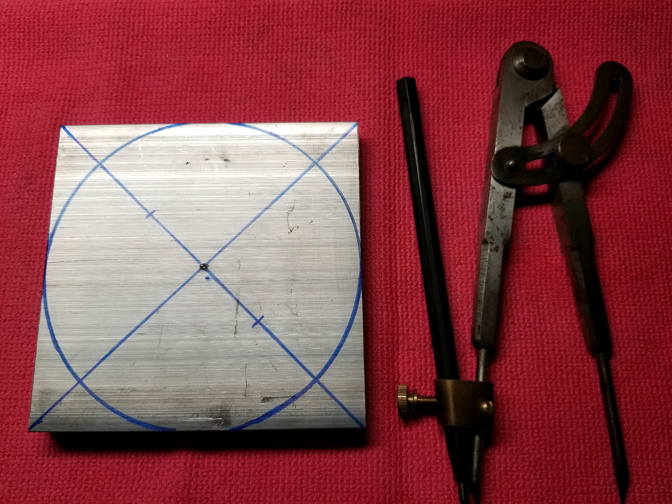
 Here I am quarter way through the rough cutting process for the New Rotor.  I'm taking a 4" x 4" x 0.5" square piece of aluminum, and cutting it into a 4" diameter x 0.5" thick round piece of aluminum.  The setup for this process is elucidated here: New Rotor.  On this first quarter of this process I was able to cut the circular marking line in half.  This is kind of impressive for my meager setup.

I will probably have to finish the Rotor on a Lathe, or with a Lathe like process in order to get the balance required to spin it.  What I am doing here is rough cutting to get the piece into a mostly circular shape before I cut the peripheral holes, and then I'll finish the circular cutting to make it pretty.

When you are cutting a big piece on a small tool you have to be careful not to overload the tool.  There are many pieces of the clamping, table movement, and spindle that are in play here, and if you try cutting too much, too fast it can cause trouble.  So, through Trial, and Error I have found a medium cutting speed, with a moderate amount of chatter.  On average I am making cuts that are around 100 mils wide, and 30 to 50 mils deep for rough cutting.  When I do a finish cut I'll be cutting around 5 mils wide, and all the way through the thickness of the part.


 Then there is also the Spindle Speed, and the Feed Speeds to consider.  All the table movements, and the spindle have Lash, and when you are cutting these clearances will cause the machine to chatter as it makes cuts.  You are exerting intermittent forces on the work piece, and then the machine relaxes between cut cutting actions.  So, your machine is regularly cutting, and relaxing, causing a mechanical resonance which is the chatter.  When you make a light cut the chatter is relatively light.  When you make a heavy cut the chatter becomes more significant.  Taking off small amounts of material allows you to have very fine cuts with tighter tolerances, although it takes a lot more passes.

 There is a setup time, and learning curve for each different piece you make.  You will have to think through the process, look at cutting speed, feed speed, feed direction, and other things before you have a setup that does what you think you want to do.  Also with any machine project you may find that your setup doesn't work the way you want it to, or is not capable of doing what you want to do in it's present state.  Work arounds, and impromptu modifications are frequently necessary to make the cuts that I want to make.  I have fabricated clamping, and holding pieces to make things before.  Sure it would be nice to have a clamping set that is universal, but it is not practical.  I try to focus on what we are cutting now, and will only buy, or make the tooling that is required for the current job.  The next job will be something you haven't thought of before, and will require something different.

Tuesday, September 13, 2022

New Rotor

 I need to make a new rotor for another generator.  This particular one is going to be 4 inches in diameter, a half an inch thick, a fabricated from aluminum.  Then I want it to be 24 poles, so I'll need to make pilot holes around the periphery in regular increments, 15 degrees.  This will be a rotating assembly, So I want to maintain the symmetry, and balance.  It will probably need a final balancing after it is assembled.  My objective here is to take a raw piece of stock, and machine it into the finished part.

This is a piece of 6061 Aluminum that I picked up at Metal Supermarket.  This place is great if you are into building metal things.  They supply, and cut metal stock to some degree, but not a machine job shop.  They have a nice scrap pile you can pick through, and find just what you need.  They had a piece of 4" x 1/2", and I got a 4" Chop.  OK, here I'm finding the center, and marking a holes for the Table Clamps.

We want to make this square thing round, so I'm going to use my machinists compass with a carbide pencil.  The carbide pencil will make a scratch on the surface of the aluminum, and then I'll trace the scratch with a marker.  This will be a manual machine operation, so I want to know where the edge of the part is.  I used a center punch to make a divot in the center for the zero end of the compass.

The tool that I am going to use to make this round part is a Rotary Table.  This is a machine table that rotates around a center axis, but also holds the part firmly in the X, and Y axes.  Notice that there is a hole in the center of the Rotary Table, and also that there are T-Slots for clamping the part.

In the bottom of the Rotary Table, at the center of rotation, is a screw which holds the bearing cap on the bearing which holds the rotating table.  There is a clearance for this screw which goes all the way through the rotating table.  I want a center pin for the part, and two table clamps.  So, I'm going to remove the existing 6mm screw, and replace it with a 50.8 mm screw.  Now, I have a center pin.

In the part I make a hole in the center of the part which has a tight clearance to the center pin.  This will be the center of the part so we can orient the part in the same place referenced to the X, and Y axes.

There, now the T-Nuts for the Table Clamps are in the T-Slots, and are ready to clamp the part down.  The screws for the Table Clamps are 5mm, and I'll add a couple holes in the part to accommodate the Table Clamps.  Now we can mount the Part on the Rotary Table.

The center pin is holding the center of the part at the origin, center of the process tooling.  Then we'll rotate the part into the mill by the turning the handle on the rotary table.  Lets get the rotary table on the mill.

Once the rotary table is on the milling table we have four axes of movement.  The milling table provides the X, and Y axes, the tool feed is the Z axis, and the rotary table is the rotary axis that is perpendicular to the Z axis on the XY Plane.  Now I am going to do some test cuts on the periphery of the part.  I want to test the stability of this setup before I try to cut the part directly.  I'm going to test the depth of the cuts that are possible to try to gauge how many passes this will take.

Here is a video about the Rotor design...