I had ordered 1.25 inch threaded rods for the studs. Once I got them I realized that the pilot holes needed to be a little deeper. Then there was another crossroad, cut the rods, or deepen the holes. At this point I had already tapped fourteen holes. So, well, the easiest rework was to make the holes deeper which was cutting aluminum. Otherwise I would have been cutting twenty four steel rods. Also, I am thinking I want more steel content around the periphery of the rotor for a little flywheel effect.
When I first cut the pilot holes around the periphery I made them 800 mils (0.8 inch) deep. Then, after picking, and buying the threaded rods I realized that the pilot holes needed to be right at 1 inch. So I have to rearrange the Mini Mill to do radial indexing again, and align the rotor to make all the pilot holes 200 mils deeper. This went fairly quickly because I had already set up this operation. After making the pilot holes deeper, I could tap all the holes deeper, then install the hardware. I did have the issue of drilling holes that were already tapped. This did work well because the original pilot holes are still there, and the threads are cut into the walls of the pilot holes, so you just have to be careful to run the drill bit between the existing threads, and not chew on the walls of the pilot holes.
The last task on the rotor was to increase the size of the center hole so that I can mount the rotor on the arbor that I will use to hold the rotor on the motor. I have used this center hole as a center in all the machining processes. So I want to change the size of this hole without affecting the position in the X, and Y axes. The right thing to do would be to put the rotor on a lathe, spin the part, and use the center chuck to hold a drill bit to bore out the center hole. So, instead, I used drill bits on the drill press to do this. I didn't firmly clamp the part so that the drill bit could center itself in the hole. Then used a series of bits to increase the size of the hole incrementally. So, in about six steps I increased the size of the hole from around 230 mils to 375 mils. Then gave it a test fit on the arbor.
The completed rotor weighs 22 ounces, which is heavier than I thought it would be. I've also been thinking about things like the flywheel effect, and the gyroscopic effect. When I spin it the torque effect from the spinning rotor will drag the frame in the same direction. So, having mounted it, and spun it a little, like five minutes ago, it does seem to be reasonably balanced to spin at low speeds. As the speed goes up, it does vibrate a little more, so when I start finishing the part I'll pay more attention to the balance on the rotor.
So, now I need to start thinking about fabricating the stator which is the collector for the system. Yeah! It Spins...
OK, I finally have the major cuts done on the CEG Rotor. This includes the radial cut where I made the round shape of the rotor, and the peripheral holes for the electrodes. The Rotor is four inches in diameter, and a half inch thick. Then there are the holes around the periphery which are pilot holes for 1/4-20 screws. There are 24 pilot holes spaced 15 degrees apart, at the four inch diameter of the Rotor. At this point it is a rough cut piece. There are more operations to perform.
Now take a look at the drawing. The outer diameter of the cut is the same, and the 24 pilot holes are there. But the drawing has more features that haven't been machined into the part yet. There are chamfers around the edge of the Rotor on both the top, and bottom sides. The center hole is a larger diameter. The tooling holes are not in the drawing. The pilot holes are the same diameter, but both the drawing, and the part do not have the 1/4-20 threads.
So, yeah, there is more work to be done in the machine shop. The center hole was first used to align the part to the center pin on the Rotary Table. When I finish the machine operations that use the Rotary Table I will increase the size of the center hole to 0.375" to fit the Arbor I picked to hold the Rotor in the assembly. Also, I will need to tap the pilot holes for 1/4-20 screws in order to hold the electrodes.
Here I have revised the CEG Rotor drawing a little. I changed the Chamfers to make the angle a little steeper. The Tooling Holes have been added. The change in the Chamfers is to accommodate the tooling holes. We want some nice flat, level areas where the clamping screws are holding the part in case there is some reason I want to put it on the Rotary Table again.
The next cut that I need to make on the New Rotor are the radial holes around the periphery of the Rotor. When I was cutting the radius of the Rotor I was using the Rotary Table as a Rotary Chuck, the idea being the Rotary Chuck holds, and turns the part while the Mill is cutting around the periphery. In that configuration the Rotary Table was horizontal.
Now I want to Drill Holes from the periphery of the Rotor toward the center of the Rotor. In this configuration the Rotary Table has to be mounted vertically on the Machine Table, and the machine will be drilling holes into the Rotor in the Z axis. So, we are still dealing with the three axes of alignment, and a rotary axis. This time we want X, Y, and rotary axes of movement clamped while we do a Drill operation in the Z axis. Then I'll loosen the clamp on the rotary axis, move the rotary axis 15 degrees, clamp the rotary axis again, and do another drill operation.
The first obstacle is the Rotor itself. The Rotor's diameter, four inches, is a little longer than the distance between the center of the Rotary Table, and the vertical mounting surface of the Rotary Table. This means the Rotor protrudes past the mounting surface of the Rotary Table by about 275 mils. and we need a short riser to get the Rotor above the surface of the machine table. We need to freely rotate the Rotor around the axis of the Rotary Table to make the peripheral holes. Also, we need to assemble the Rotary Table assembly on the Drill Press Machine Table, and not on the Milling Table. When the Milling Table is on the Drill Press there is insufficient vertical clearance to make these peripheral cuts.
Here I have used a 0.375 inch Aluminum plate to be the short riser to get the periphery of the Rotor off the machine table. The mounting screws are countersinked into the short riser plate so the short riser plate can sit flat on the machine table. Then I can slide the Rotary Table assembly around the machine table for the X, and Y axes alignment. There are two C-Clamps that secure the Rotary Table assembly to the machine table once it is aligned. I have scratched a line around the periphery of the Rotor to indicate the center of the periphery of the Rotor. I also have some lines on the face of the Rotor which will help with the X, and Y axes alignment. I used a framing square, the center of the Rotary Table, the Drill bit, and the center line of the periphery of the Rotor to perform the X, and Y axes of alignment of the Rotary Table assembly to the Machine Table, and the Drill. Blarg... Thatz a mouthful...
There is a compass around the edge of the Rotary Table. Once I had the X, and Y axes alignment locked I rotated the Rotary Table to 0 degrees. I spent a considerable about of time scrutinizing the X/Y alignment, Rotary Alignment, and depth of cut before I felt confident to make a cut. The more time you spend fabricating a part, the more valuable it becomes. As its value increases you feel compelled to overthink each following cut, and don't want to make any mistakes. This is where it ceases to be a part, and becomes an investment. Any mistakes could lead to considerable rework, or even scrapping this part, and starting again.
I have made five holes so far, and my process seems to be working well. At this point I'm going to take a break, and think through this again. I'll make some measurements on the holes I have cut, and look at the consistency of the cuts. At first glance it looks like it is going well...
This was a very aggressive cut for my Mini Mill. I was hanging over the limits, and had a couple incidents where this became obvious. The Chuck is held to the Quill with a Morse Taper. This is the way that Drill Presses typically hold the Chuck. It is perfectly OK when you are drilling, down cutting into the material, because the force applied to the Quill, Morse Taper, Chuck, and Bit is downward. This keeps the Morse Taper thoroughly seated, and locked. You will never have a problem drilling.
I call this thing a Mini Mill. OK, there in lies the problem. I'm milling, side cutting, with no downward force. The force applied to the cut is from the side, and is a cutting action so this force is cyclic causing vibration. This applies the force through the Bit, into the Chuck, on up to the Morse Taper, and into the Quill causing the entire machine to vibrate with this sideways force. Drill presses are not meant to do this. Some would say this type of cutting is not possible, and you will never get a good cut. I'm going to say that is wrong. You can use you drill press as a Mill when you keep everything tight, don't over load the machine, and make relatively small cuts that don't create excessive vibrations. The depth of the cut is relative to the amount of vibration you get, and the tool will let you know when you are cutting too deep.
In the first incident the Chuck came off the Morse Taper while I was cutting. The Chuck stopped spinning, and I had to abort the cut. There was no adverse effect because when the Chuck is disconnected from the Morse Taper it will stop spinning. In the second incident the Morse Taper came out of the Quill. In this case the Mill continued to spin, and I kept cutting, but the cut was going deeper as I went around the radius of the part. The amount of vibration, and noise that the machine was making increased. I noticed it visually, and then immediately aborted the cut. This did have an effect, but that effect was the cut got deeper, and didn't affect the radius of the cut. If anything it caused the Mill to move away from the radius of the cut.
This is the Mini Mill configured to cut the radius of this part. There are a lot of things that I can improve on this machine. I noticed that the X Axis will move with vibration, and I had to work around that issue. It would be nice to have clamps that hold the axes that don't move with a cut. There is not depth hold on the Z Axis, really another clamp, but with this cut I was holding the Z Axis with one hand, while doing the part feed with the other hand. It does have a depth limit, but not a hold at depth clamp, and that would be handy, LOL! Milling machines have a screw that goes through the Quill, Morse Taper, and Chuck which holds the rotating assembly together vertically, and that, also, would have been very handy. Then there are the bearings that the Quill is riding on. In a Drill Press these bearings are meant to handle a downward force. With a Milling Machine these bearings are capable of handling downward, and side loaded forces. I think what I am telling myself here is this I need a Milling Machine... and a Lathe...
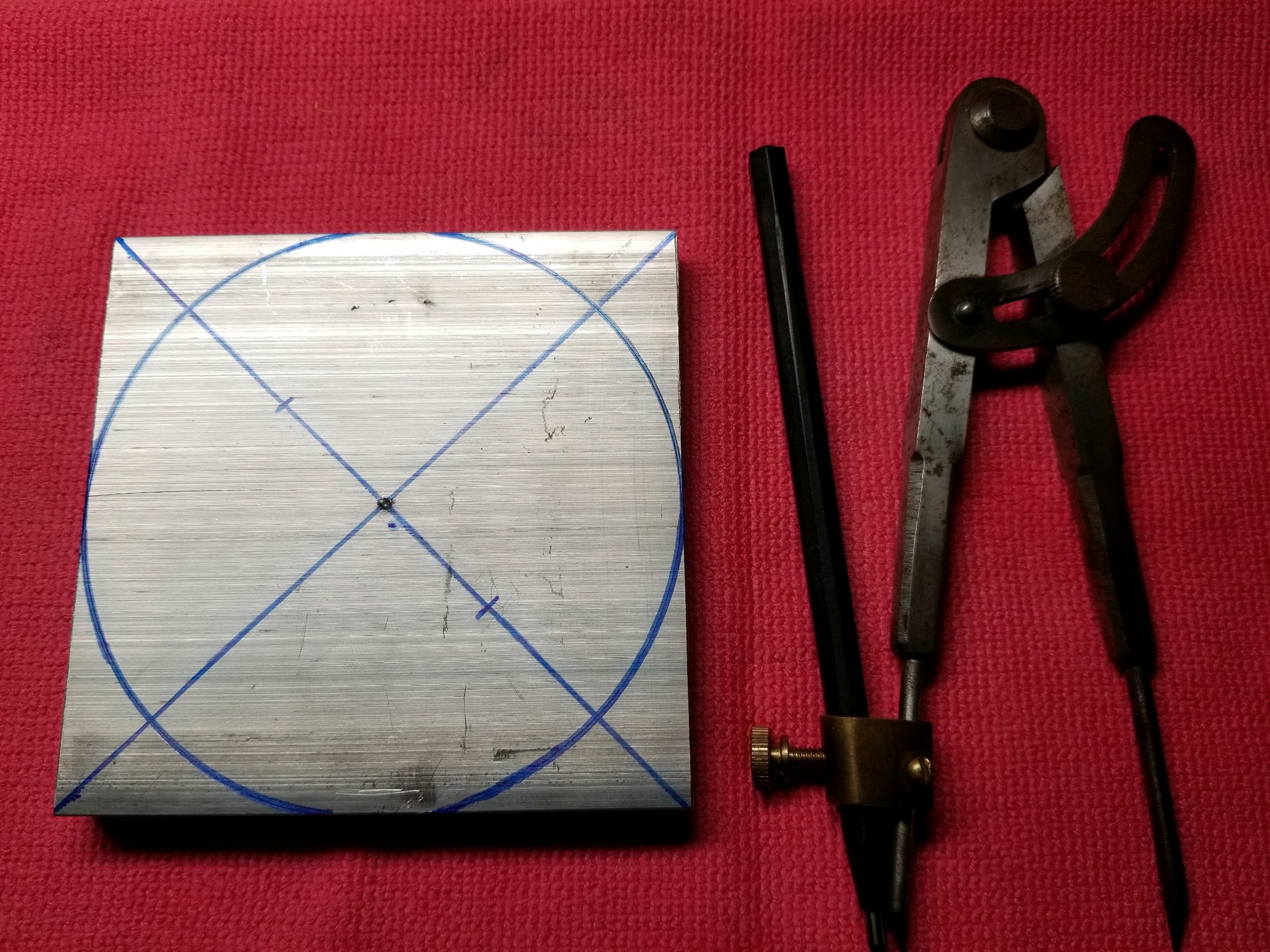
Here I am quarter way through the rough cutting process for the New Rotor. I'm taking a 4" x 4" x 0.5" square piece of aluminum, and cutting it into a 4" diameter x 0.5" thick round piece of aluminum. The setup for this process is elucidated here: New Rotor. On this first quarter of this process I was able to cut the circular marking line in half. This is kind of impressive for my meager setup.
I will probably have to finish the Rotor on a Lathe, or with a Lathe like process in order to get the balance required to spin it. What I am doing here is rough cutting to get the piece into a mostly circular shape before I cut the peripheral holes, and then I'll finish the circular cutting to make it pretty.
When you are cutting a big piece on a small tool you have to be careful not to overload the tool. There are many pieces of the clamping, table movement, and spindle that are in play here, and if you try cutting too much, too fast it can cause trouble. So, through Trial, and Error I have found a medium cutting speed, with a moderate amount of chatter. On average I am making cuts that are around 100 mils wide, and 30 to 50 mils deep for rough cutting. When I do a finish cut I'll be cutting around 5 mils wide, and all the way through the thickness of the part.
Then there is also the Spindle Speed, and the Feed Speeds to consider. All the table movements, and the spindle have Lash, and when you are cutting these clearances will cause the machine to chatter as it makes cuts. You are exerting intermittent forces on the work piece, and then the machine relaxes between cut cutting actions. So, your machine is regularly cutting, and relaxing, causing a mechanical resonance which is the chatter. When you make a light cut the chatter is relatively light. When you make a heavy cut the chatter becomes more significant. Taking off small amounts of material allows you to have very fine cuts with tighter tolerances, although it takes a lot more passes.
There is a setup time, and learning curve for each different piece you make. You will have to think through the process, look at cutting speed, feed speed, feed direction, and other things before you have a setup that does what you think you want to do. Also with any machine project you may find that your setup doesn't work the way you want it to, or is not capable of doing what you want to do in it's present state. Work arounds, and impromptu modifications are frequently necessary to make the cuts that I want to make. I have fabricated clamping, and holding pieces to make things before. Sure it would be nice to have a clamping set that is universal, but it is not practical. I try to focus on what we are cutting now, and will only buy, or make the tooling that is required for the current job. The next job will be something you haven't thought of before, and will require something different.
I need to make a new rotor for another generator. This particular one is going to be 4 inches in diameter, a half an inch thick, a fabricated from aluminum. Then I want it to be 24 poles, so I'll need to make pilot holes around the periphery in regular increments, 15 degrees. This will be a rotating assembly, So I want to maintain the symmetry, and balance. It will probably need a final balancing after it is assembled. My objective here is to take a raw piece of stock, and machine it into the finished part.
This is a piece of 6061 Aluminum that I picked up at Metal Supermarket. This place is great if you are into building metal things. They supply, and cut metal stock to some degree, but not a machine job shop. They have a nice scrap pile you can pick through, and find just what you need. They had a piece of 4" x 1/2", and I got a 4" Chop. OK, here I'm finding the center, and marking a holes for the Table Clamps.
We want to make this square thing round, so I'm going to use my machinists compass with a carbide pencil. The carbide pencil will make a scratch on the surface of the aluminum, and then I'll trace the scratch with a marker. This will be a manual machine operation, so I want to know where the edge of the part is. I used a center punch to make a divot in the center for the zero end of the compass.
The tool that I am going to use to make this round part is a Rotary Table. This is a machine table that rotates around a center axis, but also holds the part firmly in the X, and Y axes. Notice that there is a hole in the center of the Rotary Table, and also that there are T-Slots for clamping the part.
In the bottom of the Rotary Table, at the center of rotation, is a screw which holds the bearing cap on the bearing which holds the rotating table. There is a clearance for this screw which goes all the way through the rotating table. I want a center pin for the part, and two table clamps. So, I'm going to remove the existing 6mm screw, and replace it with a 50.8 mm screw. Now, I have a center pin.
In the part I make a hole in the center of the part which has a tight clearance to the center pin. This will be the center of the part so we can orient the part in the same place referenced to the X, and Y axes.
There, now the T-Nuts for the Table Clamps are in the T-Slots, and are ready to clamp the part down. The screws for the Table Clamps are 5mm, and I'll add a couple holes in the part to accommodate the Table Clamps. Now we can mount the Part on the Rotary Table.
The center pin is holding the center of the part at the origin, center of the process tooling. Then we'll rotate the part into the mill by the turning the handle on the rotary table. Lets get the rotary table on the mill.
Once the rotary table is on the milling table we have four axes of movement. The milling table provides the X, and Y axes, the tool feed is the Z axis, and the rotary table is the rotary axis that is perpendicular to the Z axis on the XY Plane. Now I am going to do some test cuts on the periphery of the part. I want to test the stability of this setup before I try to cut the part directly. I'm going to test the depth of the cuts that are possible to try to gauge how many passes this will take.
Sometimes you can be multitasking without realizing it. This time I was out cruising in Ripper at night. I had some funny electrical problems when I made right turns. The radio would cut out, and other electrical things became intermittent. The engine would lose ignition momentarily. There were sparks flying out from under my hood when the electrical issues happened. Well, this is highly concerning, and I quickly found a place to stop, and inspect things under the hood.
Once I opened the hood I was kinda disappointed that it was such a stupid failure. Something that should not happen, but does because of vibration. Ripper is a little sport car, with sport suspension, and gets Driven. So, vibration is a significant thing. Here is a shot of the battery back in January.
There are a few issues here. The first is the hold down nuts are not locking nuts, and do not have lock washers. The nut that remained, in front, seemed like it had some loctite applied to it, and the threads were gummy. The rear nut was gone, and the threads were clean, no surprise there. So, obviously we missed a spot of loctite there. But, really, loctite is not the right way to do this. Then there are the exposed conductors. I think I need to call this a design issue. There is a solid, 4mm screw, tied directly to the body, right next to the positive terminal of the battery, and also is, coincidentally, the positive terminal connected to the alternator.
In "normal" conditions the Battery Hold Down Bracket is a a couple inches away from the exposed Positive Terminal of the Battery. So, if the Battery Hold Down Bracket is holding the battery like it is designed then the Battery Hold Down Bracket will never make contact with the Positive Terminal of the Battery. Vibration makes Shit Happen. It looks like the nut on the back of the Battery Hold Down Bracket vibrated loose, and came off. This released tension on the back of the battery. The front J Bolt held the Battery Hold Down Bracket for a while, but when it slipped loose the Battery Hold Down Bracket started moving around, the Battery started moving around, and eventually the Battery Hold Down Bracket started making intermittent contact with the Positive Terminal of the Battery. That is when the funny things started happening.
This is shot of the front J Bolt. The evidence of the Arc Welding is there, and this may further indicate that there was no Loctite here. The Arcs conducted to the Bracket, and the Nut is directly adjacent to the bracket, and may have been "sticky" because it was in close proximity to the Arcing. Similar Arc scars are on the J end of this J Bolt.
To prevent this in the future there are a couple things I have done. Insulating the Positive Terminal of the Battery will prevent potential grounds from touching the Positive Terminal of the Battery. The double layer of heat shrink is a good start, but I want something that completely covers the entire terminal. Then, also, I want to prevent the Battery from getting loose in the first place.
Adding a Lock Nut, or a Jam Nut, will prevent the nuts from moving in the first place without gumming up the threads. A couple Nuts, and some Heat Shrink would have prevented this mayhem easily. Ripper is different from my other Toyota vehicles. Ripper is raw, no frills...
Well, this is new for me. This is a Flywheel Shaft Key that is split in half lengthwise. I've never seen a failure like this before. It was mechanically curious anyway. The metal is not magnetic, seems relatively light weight, but doesn't scratch easily, so maybe an aluminum alloy? I thought shaft keys were made of hardened steel. I dunno... This was an unusual failure...
So, anyway the mower would crank good. It seemed to be getting compression, and spark at first, and it tried to run a little. So, I started looking at all the areas where I have seen failures before. I cleaned the fuel system first, and flushed out the old gas. After the fuel system clean up I tried cranking it some more. Now it seems like it is not getting spark. So I inspected, and tested the ignition system. The ignition system seems to be working, so I had to dig a little deeper. When I removed the Starter Bell on the end of the Crankshaft I found the split key. Then it all became clear. It's firing, but at the wrong time, like 40 degrees late. So, anyway, I fabricated a new, steel key, put it back together, and it runs good...
Here is a shot of the Flywheel, and the Split Key before I disassembled it. Funny how a tiny bit of metal can cause a whole lot of work..
It is the hottest week of the Summer so far. This is very stressful on your Environmental Control System. Hotter Temperatures means the pressures go up, and the system runs a lot more. These conditions will cause weak parts to fail.
Look at the terminals on this capacitor. They are angled outward. They should be parallel. This is a visual indicator that this capacitor is bad. It's "puffy" which in this case means that it has failed open. When it is open no current flows. In this case it is a Motor Run Capacitor. With no current flowing to the Fan Motor, no air moves. This was the Blower Motor Run Capacitor in the interior Air Handler. We noticed that the house was getting warmer last night, and discovered that the Air Handler wasn't blowing cold air. The Compressor, and Condenser Fan were running. I did a little debugging last night, and found this Puffy Capacitor. This morning I replaced it, and had the Air Conditioner running before the Sun got high... Crisis averted...
You know that bumper sticker you put on your old car, like 12 years ago, and has been cooked on to your fender for 12 years. It seems like that would be a permanent bond, but it's not. To liberate this old, cured adhesive is actually pretty easy. In this example I have a piece of aluminum that has a product label on it. I'm starting to surface finish the piece, and this label is in the way. It's been on there for around 13 years.
There are chemicals that are specifically formulated for adhesive removal, and I hate all of them. They are usually potent VOCs that are both flammable, and noxious. So, what is the alternative? Heat... It is an electronic solvent. How do you loosen something up at an atomic scale? Heat... It causes the atoms to expand, and you get mobility. With mobility the adhesive gets gummy again, you can manipulate it again, and remove it easily. My process is to use a heat gun, or hair dryer, and warm up the old sticker. Then, in this case, I used a plastic scrapper to prevent gouges in the aluminum. There is a residue of the adhesive left on the aluminum after scrapping the label, and adhesive off the part. I use penetrating oil to remove the residue. Then to remove the penetrating oil I'll use a degreaser like 409, or ammonia. Now I can get back to the surface finishing...
After refurbishing the original RX300 driver's seat, now I have an extra RX300 driver's seat. Originally I got this seat because the seat in the RX300 was worn out, and covered in duct tape. This link, RX300 Seat Renewed, covers the work I did on the original driver's seat in the RX300. This thread is about the spare seat that I used in the RX300 when I was working on the original seat. So, anyway, now I've got an extra RX300 driver's seat. I should do something with it...
So, my wife suggested that I get a new office chair at my desk. The old chair is 25 years old, and broken in many ways. It is so bad I don't want to publish a picture. So, like a lot of the stuff I build there needed to be some adaptation to use the RX300 Seat in the Office Seat role. It needs wheels, so I can roll around the house. I need the interface between the wheels, and the seat. Also, I need a theme to tie this automotive part into our home, and the office, so Fence Posts it is...
I want to do this cost effectively, and utilize the materials I have at hand as much as possible. In our home we have a lot of rustic furniture that it made from aged Cedar, and in order to tie this chair into the house I am going to use big hunks of aged Cedar. No, question there. So, I chopped up an old fence timber, and it will become the frame for the Office Chair.
Of course I want this platform to be very strong. The RX300 Seat is really heavy because it is a full power seat with five motor control systems. Sure, I could have got a light weight seat, and trimmed down the size of the base, but all at a cost. I wanted to use materials that I have at hand, but as few new parts as necessary.
But, I did have to get some new parts, all hardware. I used 3/8" x 6" Lag Screws to put the frame together. Then, I picked some 4" rubber casters on steel mounts, like you would find on a piece of equipment, or a big tool box. The heavy platform holds the seat well, and together they have the heft of a high quality chair, with an advanced level of comfort.
Next I needed to connect the seat to the platform. I like to use 1/2" hardware in my projects, so, that is the choice here as well. The size of the platform was dictated by the mounting pads on the seat, and I had to factor in the screw paths. All the hardware seems to fit alright.
The next task was to interface to the electrical controls. The motors that control the positions of the seat are all 12 Volt powered. So, I needed a wiring diagram for the RX300 seat. This took a little digging on the Interwebz, and resulted in a similar wiring diagram for a compatible seat.
The RX300 Seat has the motors that control the seat positions. and the switches that control the motors. So, in order to move the seats I needed to supply 12 Volts, and Ground to the right connections on the seat harness connector that goes to the body wiring harness. This was fairly simple, and I used a shop power supply to test the seat controls. My little bench top power supply provided enough current to run the Slide, and Tilt motors in the seat, but not the seat elevation. I also tried this with a 7 Amp Hour battery, and it was still deficient to run the elevation controls.
So, I need a little bigger power supply, or bigger battery, but then I should be able to use all the controls. This is a little more work that simply buying a new office chair. But, this is something that is customized for me, by me, and I like it...
Oh look! It's another broken small gas engine. This one is special, well, sort of. It's a Briggs and Stratton Platinum Engine. It has overhead valves, which is still kinda new to me for an American made engine. Briggs and Stratton held on to the flat head design in the small lawn mower market right up until the turn of the Century, 1997. So, lets Rip into it...
Usually when I start debugging a small engine I want to try to start it. Then I can evaluate things like the ignition, and fuel system condition. On this one the Start Handle was missing. So, I guess we are going to trouble shoot the Starting System first. I removed the engine faring, exposing the Recoil Starter. Then I removed a few more screws, and the Recoil Starter is removed from the engine.
I disassembled the Recoil Starter assembly, and found damage. There is a keeper that holds the end of the recoil spring which is damaged, and it not holding the spring. This means the starter is not working, in multiple ways. The Pull Cord has been cut, the Pull Handle is missing, and the recoil spring keeper is damaged. This is an indication of long use. I was stuck here for a time looking for a part. But then realized that I have another mower with a very similar engine, and I could borrow the starter off the good working mower to test the broken mower. How fortuitous...
After swapping the Recoil Starter Assembly from the good working mower to the broken mower I was able to do a little more troubleshooting. The engine cranks, and I am reasonably sure that it is getting compression, and spark. When you pull the cord you can feel the compression stroke of the motor because the cord gets a little harder to pull periodically. You can hear the carburetor "whine" on the intake stroke, and you can hear the exhaust exhale on the exhaust stroke. This tells me that the rings, and bore are generally doing their job by making compression, and that the valves are sealing. I tested the spark by spraying some Carburetor Cleaner in the intake of the Carburetor, and cranking the engine. This resulted in the engine briefly running, and then shutting off.
With the testing I have done so far it looks like my Briggs and Stratton small engine has a fuel system problem. The fuel is not being metered properly into the engine, and the engine will not run because of this. The engine is not getting enough fuel to run. This mean we have to dis-assemble the carburetor, and see if we can find a problem. First there are two linkages we must disconnect from the carburetor.
Modern Mowers have automatic features that make the operation of the mower easier. In the picture above is a feature that engages the choke on the carburetor when the mower is cold. It is a thermal actuator connected to the muffler. Its function is to push the choke open when the mower warms up. For what we are doing here we need to remove this linkage from the carburetor so that we can remove the carburetor. So we need to remove three screws from the muffler heat shield, and two screws from the muffler, and then we can disconnect the linkage.
While you have these exterior pieces removed from the engine you can clean those spaces you would not normally have access to. Maintenance is largely about cleaning stuff, like the air filter, the fuel filter, and the little bits that get grimy...
The Air Cleaner Assembly holds the carburetor in place in conjunction with the bracket you see around the carburetor. The flow connection of the carburetor is a tube, with an O-Ring. I am beginning to like the simplicity here. Also, it is an all plastic carburetor, and is the first plastic carburetor I have worked on. It's kinda weird, but also makes sense to my engineering brain.
OK, now that the carburetor is detached we can get on with the task of determining our fuel system problem. At this point I have to note that I have not found a discrete fuel filter. Usually with lawn equipment you need a fuel filter because of the excessive amount of debris associated with lawn service. This mower does have a large, pleated air filter, but not a fuel filter. Maybe there is an inlet screen on the carburetor fuel inlet.
Small engines used for lawn mowers run at a single speed, and the carburetor can be simplified because of this. This carburetor is very basic. I think it still has idle, and run circuits, but I have to admit it is still a little mysterious to me. There are two screws to remove the float bowl, and then inside I found what appears to be a Jet Module which contains the metering jets for the idle, and run circuits.
There are three tubes on the Jet Module, and I think that two of them are the idle, and run circuits. Then I am assuming that the third is a vent, but I am not sure at this point. So, I am going to clean the Jet Module, and the Carburetor in general, and then re-assemble everything, and give it a Krank...
All the bits, and pieces go back together in reverse order, just like in the old car manuals, LOL! Easy right? No, really this is a very simple engine, and I think if we can get the Gas to the Bang Box itz gonna Krank...
I want to note some other features that I found on this fuel system. It has a Positive Crankcase Ventilation tube that runs from the crankcase to the air cleaner. There is a Gas Tank Vent that runs from the top of the gas tank to the air cleaner. Compared to other small engines I have worked on, this one has an oversized muffler. I wear headphones when mowing, so having less external noise is good.
I also want to note some things that are not on this engine. There is no Primer Bulb, which was once used to circulate fresh gas into the carburetor. Also this engine does not have a user accessible throttle adjustment. Old mowers had a throttle, and I guess these newer mowers use the governor to regulate engine speed. New mowers are more powerful, and less troublesome, I guess...
Well, looka there... I inspected the Jet Module carefully before I cleaned it, and it looks like the actual problem was there. Two of the jets looked open, but the one in the middle seemed clogged. After I sprayed with with the carburetor cleaner the "jet" in the middle opened up, and I got that warm, fuzzy feeling of success. The two jets on the ends have metal inserts, like they are used to precisely meter fuel, while the one in the middle was just plastic, and kinda seems to be a vent tube. I have to look into Briggs and Stratton Plastic Carburetors a little more. OK, Happy Mowing...