I need to make a new rotor for another generator. This particular one is going to be 4 inches in diameter, a half an inch thick, a fabricated from aluminum. Then I want it to be 24 poles, so I'll need to make pilot holes around the periphery in regular increments, 15 degrees. This will be a rotating assembly, So I want to maintain the symmetry, and balance. It will probably need a final balancing after it is assembled. My objective here is to take a raw piece of stock, and machine it into the finished part.

This is a piece of 6061 Aluminum that I picked up at Metal Supermarket. This place is great if you are into building metal things. They supply, and cut metal stock to some degree, but not a machine job shop. They have a nice scrap pile you can pick through, and find just what you need. They had a piece of 4" x 1/2", and I got a 4" Chop. OK, here I'm finding the center, and marking a holes for the Table Clamps.
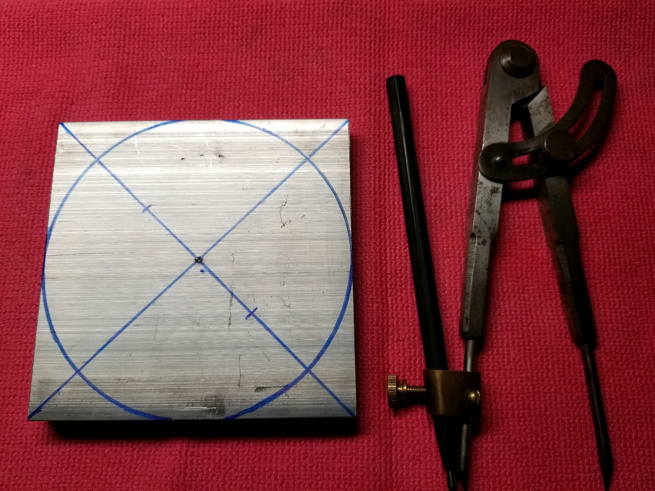
We want to make this square thing round, so I'm going to use my machinists compass with a carbide pencil. The carbide pencil will make a scratch on the surface of the aluminum, and then I'll trace the scratch with a marker. This will be a manual machine operation, so I want to know where the edge of the part is. I used a center punch to make a divot in the center for the zero end of the compass.

The tool that I am going to use to make this round part is a Rotary Table. This is a machine table that rotates around a center axis, but also holds the part firmly in the X, and Y axes. Notice that there is a hole in the center of the Rotary Table, and also that there are T-Slots for clamping the part.

In the bottom of the Rotary Table, at the center of rotation, is a screw which holds the bearing cap on the bearing which holds the rotating table. There is a clearance for this screw which goes all the way through the rotating table. I want a center pin for the part, and two table clamps. So, I'm going to remove the existing 6mm screw, and replace it with a 50.8 mm screw. Now, I have a center pin.

In the part I make a hole in the center of the part which has a tight clearance to the center pin. This will be the center of the part so we can orient the part in the same place referenced to the X, and Y axes.

There, now the T-Nuts for the Table Clamps are in the T-Slots, and are ready to clamp the part down. The screws for the Table Clamps are 5mm, and I'll add a couple holes in the part to accommodate the Table Clamps. Now we can mount the Part on the Rotary Table.

The center pin is holding the center of the part at the origin, center of the process tooling. Then we'll rotate the part into the mill by the turning the handle on the rotary table. Lets get the rotary table on the mill.

Once the rotary table is on the milling table we have four axes of movement. The milling table provides the X, and Y axes, the tool feed is the Z axis, and the rotary table is the rotary axis that is perpendicular to the Z axis on the XY Plane. Now I am going to do some test cuts on the periphery of the part. I want to test the stability of this setup before I try to cut the part directly. I'm going to test the depth of the cuts that are possible to try to gauge how many passes this will take.
Here is a video about the Rotor design...
No comments:
Post a Comment