Monday, July 5, 2021

Drill Press Bearing

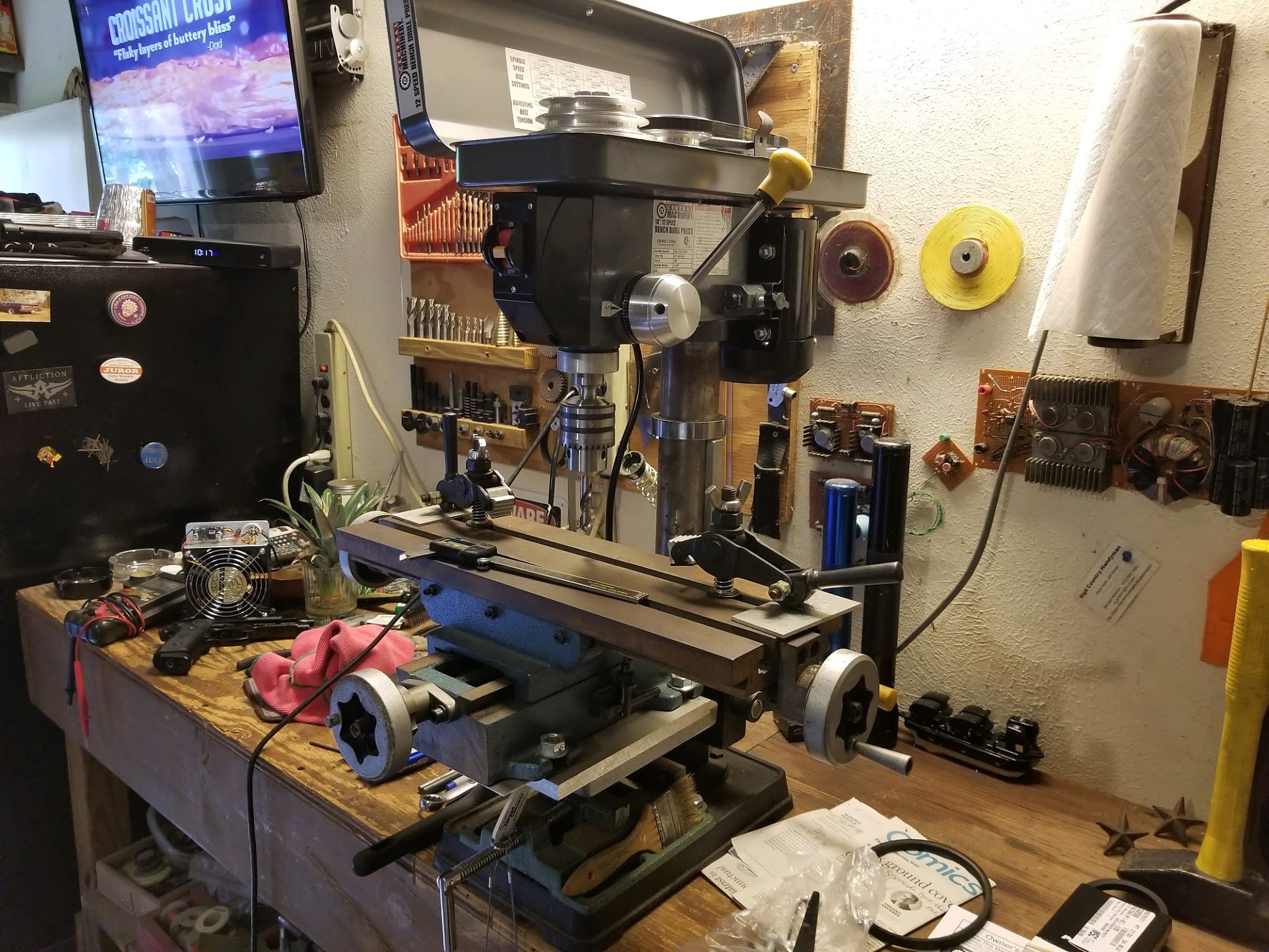
 I bought this Drill Press in July, 2010, and have been using it continuously since then.  It has been a cornerstone of my Metal Shop in fabricating multitudes of projects for many jobs, and home projects.  So, I was kinda of sad to see it loose a bearing in the drive motor.  It should be a simple fix, just replace the motor.  Well, that is where everything got difficult, and I had to get creative.  This is a shot of the Drill Press when it was new in 2010.


 It's nothing special, just a cheap bench top Drill Press from the import store.  This one got some special attention for fabricating my nefarious plans, LOL!  I added a Cross Slide Table to it so that I could do milling.  This was before I know what was possible for the little Drill Press.  Side Cut Milling doesn't work very well on a Drill Press because it's bearing are setup for plunging into the material (drilling), and not side cutting (milling).  So the Cross Slide Vice wasn't a good choice, but I soon found something that would be helpful.  This is the Mini Mill configuration with the Palmgren Milling Table.

The Palmgren Milling Table allowed me to do some limited milling, and really opened up what I could do on a Drill Press.  I could now do side cutting to clean up slots, edges, and do chamfering.  I could also now do milling processes in soft materials, like plastic, and wood.  One of my latest projects was making countersinks in a one inch thick aluminum plate, which it did easily.

So, over the last week I noticed the drive motor started making a knocking sound.  I spent some time trying to diagnose, and remedy the problem, but after a while it became apparent the bearings in the drive motor were worn out, and I needed to replace them.  Simple right?  We go over to the import store, and buy a new set of bearings, and then install them, LOL!  Your Drill Press should not make this sound...

I tried to find a replacement motor first.  Well, the import store doesn't sell a replacement motor that fits this drill press.  Huh?  Well, that's convenient...  So, I went to another place to get a replacement motor, and they had one, but it was $200.  The whole Drill Press was only $150 at the import store.  Uulgh...  So, I was kinda stuck there for a while.  I looked at replacing the entire Drill Press, perhaps a little better, and was fascinated with that for a while.  Ultimately I decided to buy the same drill press from the import store.  It was the cheapest option that would get my Mini Mill working again.
Why the heck would you want to do that?  This Drill Press has done everything that I needed it to do for 11 years.  What happened to the drive motor is an expected breakdown, and would have happened eventually, and I guess last week was it's time.  So I get a replacement motor, but also a full set of spare parts.  I can repair the bearings in the first drive motor at my leisure, and then I have a backup motor.  Also this gives me an opportunity to disassemble the spindle, and look at its bearing configuration.  Maybe I can change the bearings, and make my little Mini Mill even better at side cutting.  I have also been toying with the idea of adding stepper motors to the milling table.  OK, mo later, back to the Metal Shop...

Monday, May 31, 2021

Toilet Tank Spacer

 There is a situation where the Drain Pipe for the Toilet isn't in quite the right place, and it positions the Toilet a little too far from the wall.  Then when you install the Toilet Tank it leans back against the wall.  This put abnormal pressure on the Tank to Bowl Seal, and it will start to leak after a while.  I'm sure there have been many things used for spacers.  I found this recently, and it makes the Tank Gap a snap, LOL!

I had the Tank Gap for a long time, and wound up having Tank to Bowl seal problems, and leaks.  Mind the Gap!  er, uh, Mend the Gap?  This is a very simple, solid solution, with no hardware.  It's just a couple of molded plastic pieces that you cut to length, and press fit.  After the installation the Tank is vertical, and solid, no rocking, or shifting.

The before, and after, this is a great product...


Friday, May 14, 2021

Renewed Guitar Stand

 The Guitar Stand is getting close to 25 years old, and it showed.  The padding on the rods that hold the guitar are all dried out, and cracked.  So its time for a refresh.  The years of crud on the metals were no match for Ammonia.  It's shiny again.  As for the padding on the bars I used some automotive tubing that fit the 5/16 inch rods.  It looks cool again, and I have put automotive parts on my guitar stuff..  LOL!

Before the refresh it was looking pretty sad.  We are now in the second renaissance so it is a good time to be renewing old things.  I've been kinda busy with it...


Sunday, May 2, 2021

Another Post

Usually I am playing with Fence Posts.  This Post is a little different.  I cobbled together parts to assemble a microscope.  I have a nice Leica Microscope Head, an Illuminator, and a Swing Arm to hold the Microscope.  But, what I didn't have is the Base, and Post to hold the Swing Arm.  The Microscope is fairly difficult to use if it is not supported.  Salvage time...

So I found a one inch diameter post that has a two inch diameter aluminum mount.  There are four M6 screws that hold the post mount to the plate.  Then I also found a nice base plate which is one inch thick aluminum, but it doesn't have holes for the post mount.  Off to the machine shop...

This piece is kinda big for my Mini Mill.  I was able to clamp it to the table with no problem.  The trouble was with the Z Axis.  My regular drill bits were too long to get the aluminum piece under the bit.  I had to get some Screw Machine Length" Drill Bits.  The regular hardware stores were no help with this.  I got, "Huh?  Wuts that?"  Even at Ace...I did find what I was looking for at CDC Surplus, which is The Machinist's Candy Store over in Richardson.  Screw Machine Length Drill Bits are shorter, like Mills, and harder that regular drill bits.  They also made this job possible on the Mini Mill.

So I had to make a clearance through hole so the M6 screws could go all the way through the plate.  Then I had to make some really deep countersinks.  I wanted to use the hardware that came with the Post, and not chase down additional hardware.  This means that I had to make the countersink 0.7 inches deep.  I wanted the hardware to be recessed because the screw heads are on the bottom of the plate, but had to make them extra deep because the M6 screws were only around half an inch long.

So, this worked, and I was able to get all the screws in the first time, which is a big deal.  Measuring the part, marking the part, and getting the holes started in the right location are critical to get big pieces, and big cuts to work right the first time.  The through hole cuts were 17/64" through an inch of aluminum.  Then the countersink cuts were 7/16" through 0.7 inches of aluminum.  All four screws went in, the first time...  Score!


Sunday, March 21, 2021

Flux Suckers

 Flux Suckers are now for sale.

Airflow up to 200 CFM evacuates solder smoke efficiently.

Small footprint saves valuable assembly space real estate.

Rugged design withstands heavy use, and abuse.

Developed in conjunction with a Beta Test Team over 5 years.

This is The Best Solder Smoke Evacuation Fan you can buy.

$130, shipping or delivery available.


Thursday, March 11, 2021

Flux Suckers

 I've been building the first production run of the Flux Suckers.  This is my solder smoke extraction fan that I have been developing over the past 5 years.  This whole idea started when I had to start using a solder with no clean flux.  The solder smoke was acrid, and caused me to have a autonomic cough response whenever I got the solder smoke close to my face.  Gotta keep that smoke away, so I needed a good solder fan to do that.  And, Flux Suckers was born...

It started with selfish intent, I gotta keep that smoke away from me, but I could see that the other solder technicians around me had the same problem.  The acrid no-clean solder smoke was irritating them as well.  So, I started building copies, and developing the Flux Suckers.  The very first Flux Sucker was very sophisticated.  It had a PIC Processor which used Digital Pulse Width Modulation to bias a MOSFET which was driving the Fan.  It was very effective, but also very expensive.  One of my first tasks was to knock the bottom out of the cost, so I changed the speed control to a Linear Regulator scheme.  At the time I was building the Flux Suckers with salvaged computer case fans.

I also used all sorts of salvaged parts to make the control head, and base.  This gave my Flux Suckers a ragged appearance seeing how they were literally made from salvaged parts, and junk.  I recently scrapped out all the old Flux Suckers, and reminisced about all the crazy impromptu designs I had come up with.  Over the last year or so I wanted to take the Flux Suckers to a manufactured product level.  This lead me to generate a Bill of Materials in order to reliably source cost effective parts.  I also made mechanical drawings to make the parts that needed to be fabricated uniform.  The performance was also a big issue.  I wanted Flux Suckers to be cost effective, but also perform at a levels where there are no complaints.  So now Flux Suckers has a switching regulator that can deliver up to 3 Amps.  The fan is a very powerful server fan which delivers up to 200 CFM, maybe about three times what it normally needed to serve this function.  In normal operation the Flux Sucker is relatively quiet, but you can crank up the power when you need it to handle a bigger task.

Most of the labor involved in manufacturing Flux Suckers is the metal parts that I fabricate.  On the early Flux Suckers I would literally use double sided tape, or the hook and loop fastener to attach the control board to the top of the fan.  This is something that evolved a lot, and required a significant amount of thought.  The modern Flux Sucker has a control head.  It is a piece of angle aluminum where the electronic controls are mounted.  It holds the switching regulator, a switched potentiometer, and a LED indicator.  So all of these parts require mounting holes.  I buy a piece of angle aluminum stock, chop it to length, mark the hole locations, cut holes, shape the profile, and finish each piece before assembly.  The latest control head has a brushed finish on its face.

Saturday, February 27, 2021

Water Vitalizer with a new motor

 Originally my prototype Water Vitalizer was using a motor that was salvaged from a broken Ryobi drill.  It was a good use of salvage parts, but not practical in that I would have to find an obsolete Ryobi drill, and salvage the motor out of it.  So,I got an off-the-shelf surplus drill motor, and adapted it to the Water Vitalizer.  This required that I modify the mounting bolt pattern for the new motor, and modify the air vent holes in the mounting plate to accommodate the vent holes in the new motor.  So I marked up the motor mounting plate, and then used the Z.Monkey Mini Mill to modify the Motor Mounting Plate on the Water Vitalizer.

I call this process Nibbling, or making Nibbles.  There is a tool called a Nibbler, and it is different than what I am doing here.  I literally mark the plate with the areas I want to cut using a Blue Sharpie, and then use an End Mill to nibble out the areas I want to remove.  The Milling Table let me make some very precise little cuts, and I can sneak up on the patterns, or shapes I want easily.  This motor mounting plate is 1/8" aluminum, so it is relatively easy to cut.  Then after I get the new motor pattern cut into the motor mounting plate I put the Water Vitalizer back together for a test.  It's been running for a few days now, so I think I'll say it is working good...