Tuesday, March 21, 2017

Leavitt Garden

We had a plan to build two 8x4 Raised Garden Boxes on Saturday.  Casey had picked a design out of a Garden Manual, gathered the materials, and started working on the Boxes before I had arrived.  It quickly turned into a major undertaking when we all realized the volume we were dealing with.  Kevin and Casey went to get two cubic Yards of Raised Bed Soil.  That's 54 cubic Feet of Dirt.  It completely filled the bed of his Dodge 2500 HD pickup.
We had to start by marking off the area where we wanted to put the Raised Beds.  This spot is on the North West corner of the yard, and has good light all day long.  We used frame pieces to mark off the area, and then started using my new Pick Mattock to remove the Bermuda lawn.
 This was a fairly warm Spring Day, perfect for building another Organic Garden.  After removing the grass from the area, we dug the post holes to anchor the frame to the ground.  We didn't use concrete, instead we filled the holes with the native clay soil, then compacted the soil around the holes.  The posts are well planted.
After thee posts were planted then we added the sides of the box.  The Raised Bed is three 2 x 4s deep, about 10.5 inches.  We picked up two cubic yards of soil.  The Raised Bed is 16 feet long, 4 feet wide, and 10.5 inches deep (0.875 feet).  That works out to 56 cubic feet, and the two cubic yards of soil is 54 cubic feet, so the load of soil almost perfectly matched the size of the box.
So during the construction process the design of the Raised Bed changed, and it became on 16 foot, by 4 foot box.  The number of posts changed, not a bad thing.  The finished Raised Bed has a clean, and symmetrical look.  Now we are ready for some Tomatoes.
After we finished the Raised Bed we made some Smoked Chicken Tacos, Vegetable Kabobs, with fresh Pico de Gallo.  We all needed some proteins after this job...

Z Gate

This is the follow up to Double Stump.  I had decided to use 6 x 6 Posts, and did the same on the other side of the Z Gate.  So the mounting point for the Z Gate hinges is extremely solid.  This contrasts the way it was, saggy, and broken.  This time I build a little frame around the post to contain the concrete, and get the joint between the concrete, and the post off the ground.  This way water cannot stand at the base of the post.
Yes that was a muddy mess, but in the end ir is very nice looking.  Another thing about the Z Gate is the "Z" configuration.  I did several things to the Z Gate to give it dimensional stability.  There are two cross boards at the top, and a cutout for them in the side frame pieces.  They are connected with 3.5" screws.  The bottom cross piece also has 3.5" screws.  Then the "Z" piece crosses from the bottom hinge side to the top swing side, also secured with 3.5" screws.

The previous gate didn't have a frame.  It was all hanging off the 2 x 4 with the hinges attached, and nailed together.  So, over time the wood shank, the nails became loose, and the gate started to sag, causing the bottom to scrape along the ground.  The Z Gate is designed to maintain its shape, and not fail this manner.
Then the biggest job for the Z Gate is to contain Harlz...

Monday, February 6, 2017

Double Stump

Had some fun playing in the dirt this weekend.  Behold...  The Double Stump...

Saturday, December 24, 2016

Let It Snow!

Ironically while making a "Let it Snow" sign for the front yard, its 72 degrees in Dallas.  We have an old "Let it Snow" sign that is totally done for.  It's probably 15 years old, and just falling apart.  So, I hatched a plan to replace it.  Do ya think I could find a replacement?  Not a chance.  I probably spent a day finding the parts, and assembling it.  But now its done, just in time for a Tropical Christmas.
Looks cooler at night...

Sunday, December 11, 2016

RX300 Windows Tech Brief

There are probably many suitable relays available from several manufacturers.  I picked a Panasonic Relay because the RX300 was originally fitted with Panasonic parts.  The ACJ2112, available at Mouser Electronics, seemed like the best pick, but there are others that will work in this situation.  What you need first is the datasheets for the specific relays that are being cross referenced.  The CR2-12V is the original relay, and the ACJ2112 is the replacement.  These are excerpts from the datasheets.  This is the original CR2-12V Relay...
You are specifically interested in the PC Board pattern, and schematic of the Relay.  This gives you the information about how the relay is wired onto the Door Control Board.  Now here is the ACJ2112 part specification.
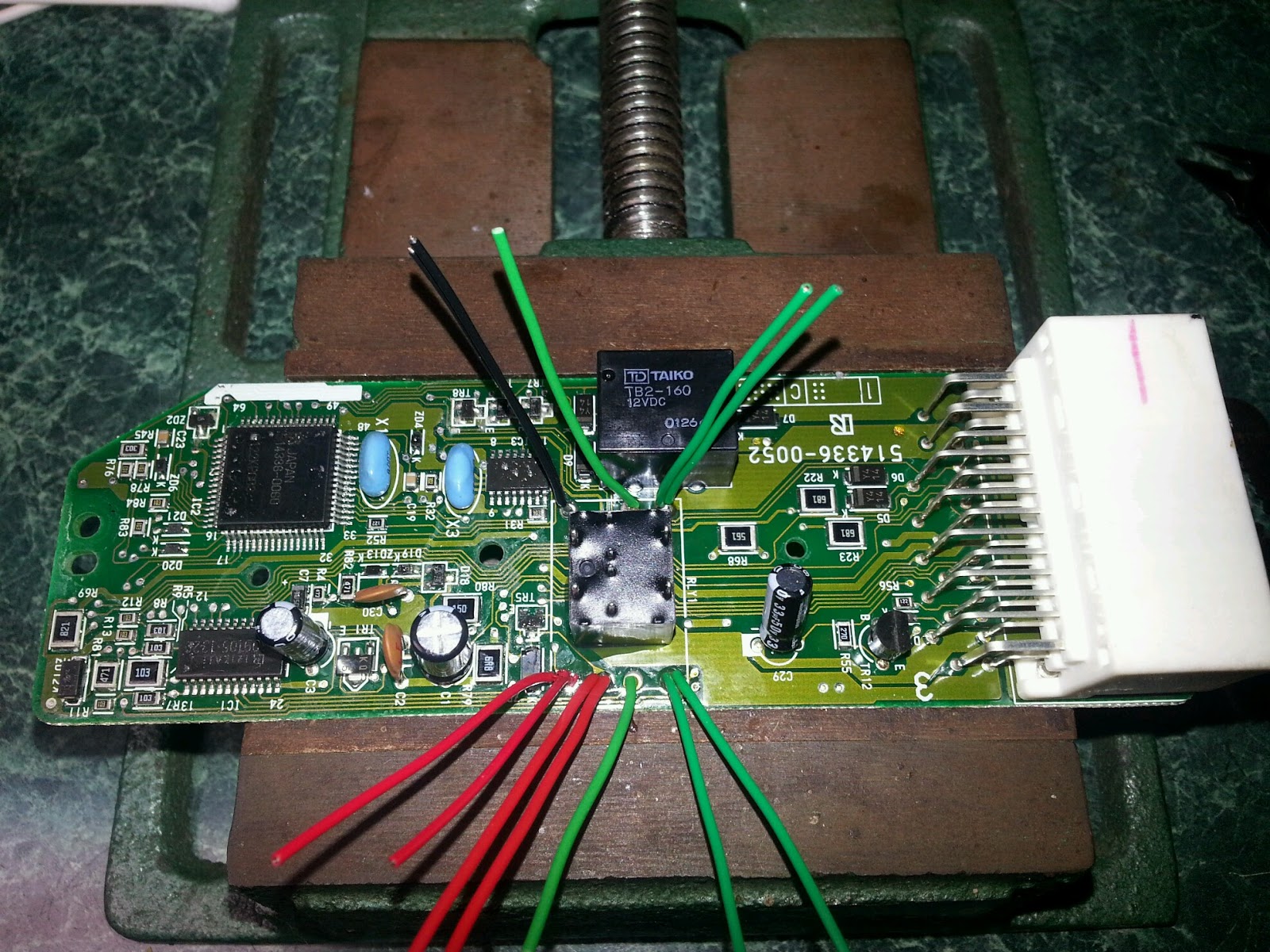
Note that the ACJ2112 is considerably smaller than the CR2-12V.  Both parts are shown from a bottom view, but we will be using the Dead Bug Technique to wire in the replacement relay, so the connections will be mirrored vertically relative to the CR2-12V part specification drawings, example below.  Here is a shot of the Dead Bugged Relay.
Alright, this is where it gets tricky.  You are looking at the top side of the circuit board, so the CR2-12V footprint is mirrored vertically.  Then we are going to put the ACJ2112 down, up side down, within the CR2-12V's footprint, with the common contacts oriented to the right, to the window motor.  The Normally Open, and Normally Closed contacts go to the power supply side.  Then the coil contacts are in the middle.

I cropped the schematic diagrams out of the part specifications, and reoriented them to the positions they have in the photo above.  Notice the way the common contacts are touching the Normally Closed side of the relay, and how they are both on the top.  Here we have aligned the relay switching position.  This is how you verify that the up switch will make the window go up, and not down.  There are three opportunities here to wire this backwards.  The common connections go to the window motor, wire them backwards, and the window works in reverse.  Like wise if you wire Normally Open, and Normally closed backwards the window also works in reverse.  If you get the control signals to the coils wired backwards the window works backwards.  So you really need to pay attention to which wire goes where.

As for wiring, the heavy current wires are Commons, to window motor, and Normally Open, and Normally Closed, which go to the power supply.  These wires can carry 20 Amps, so they need to be at least 18AWG, 16AWG would be better if it will fit.  I plan on using 18AWG Solid wire to connect the heavy current terminals.  Soldering large wire like this will require a soldering iron with enough power to heat the larger mass of the wire, and circuit board.  If you are having trouble getting the solder to flow, find a more powerful iron.  The solder joints carry current, and need to be flowed correctly.  The coil wire, as you can see in the specification above, only carry about 50 milliAmps, so the control wires to the coils can be 24AWG Solid wire.  I used a 5 minute epoxy to glue to ACJ2112 to the circuit board.

This Tech Brief takes time, and effort to produce.  There is a Donation button at the top of this page, please contribute to my effort to keep Kick Ass Toyotas (RX's specifically) working like they should...


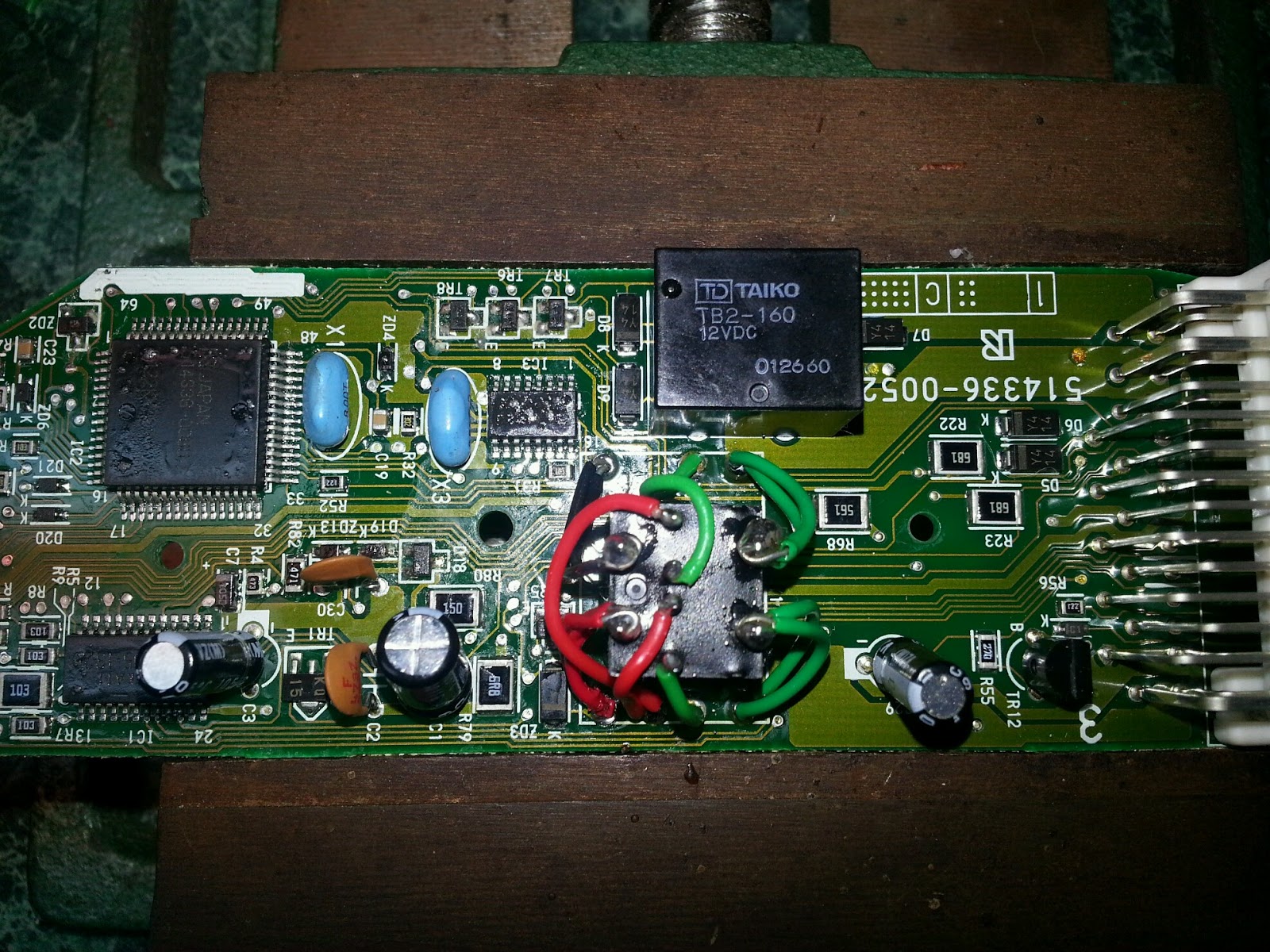
 Ultimately I wound up replacing these with aftermarket boards.  There are a lot of cheap Knock Offs now.  The first sucked, literally, and would drain the battery.

The second worked better, but has a glitchy thing with the locks when I close the driver door.  Cheap Knock Off are just that.  It would be nice to get some genuine Toyota parts, LOL!

Wednesday, December 7, 2016

RX300 Windows

Victory!  I have been trying to repair the intermittent behavior with the RX300 Windows for a long time.  Even after identifying the bad part there was a struggle to get a replacement.  The trouble is the Power Window Relay in the Door Control Panel.  The Relay is worn out, and is intermittent.  The obvious thing to do, replace the relay, was problematic in that the part went obsolete in 2010, and the remaining supply is pricey.  The original part is a Panasonic CR2-12V Dual 1 Form C Relay, designed specifically to be a power window relay, and PCB mounted to boot.  This is the reworked Door Control Board with the new Power Window Relay.
The replacement is a newer Panasonic ACJ2112, Dual 1 Form C Relay, designed specifically to be a power window relay.  The good news is that this part is smaller, and easily fits within the footprint of the old part.  The bad news is the pin out is not the same, and we'll have to wire the part in, not a big deal.  I searched a long time for this part, and it appears to be the right part for the retrofit.  The large current terminals on the new relay are oriented the same as the original relay when they are upside down.  This means the designers were savvy to the eventual retrofit.  Here is a shot of the original relay.
The original relay is the CR2-12V on the Door Control Board.  The replacement ACJ2112 is to the bottom.  The circuit board had heavy through holes for the relay, but you want to be careful when you desolder the original relay to avoid damaging the circuit traces.  Then I defluxed the board to remove the flux from the solder wick.  I compared the datasheets for the CR2-12V, and the ACJ2112 to figure out the right orientation for the new part, so the wires would go down as straight as possible.  Then use Epoxy to glue new new relay onto the circuit board, upside down, oriented in the middle of the footprint of the original relay.
I'm using two 22AWG Solid Core wires for the connections that carry the window motor current.  The Coil wires are 24AWG Solid Core wires.  I'm gluing the relay down, using solid wire, and making the solder joints as robust as possible in order to withstand vibration.  This is an automotive application, lots of vibration occurs, gotta make it hard.

The passenger side window is the worst one in the case of the intermittent operation.  So it is the first one that I attempted this repair on.  It worked right the first time, LOL!  I carefully thought through the replacement using the datasheets for both the relays, got the wires worked out before I started the operation, and double checked my ideas again during the operation.  Now I have three more to repair, presently.  I bought extra parts to fix more if I need to.  Anyone having RX300 widow trouble?